
 设为首页
设为首页 加入收藏
加入收藏 联系我们
联系我们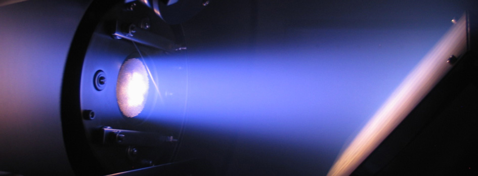

Physics of Ion Beam Source
Introduction
Ion beam technology was developed at NASA in the 1960’s as a means of producing thrust on spacecraft. Several spacecraft have used ion beam thrusters for station keeping and trajectory control. Recently, the spacecraft Deep Space 1, demonstrated the long duration performance capabilities and propulsion advantages of ion-beam thrusters. There are numerous publications about ion beam thrusters and some are given here for the interested reader [1-3].
Ion beam sources also have numerous terrestrial applications. In the past decade, ion beams have been used for depositing oxides, diamond-like carbon, and other useful coatings on mechanical and optical hardware. They have also been used to fabricate the read/write heads used in computer hard-drives and thin-film optical filters for telecommunication applications. A select few publications involving ion beam deposition technology are given here for the interested reader [4-7].
For this brief overview, it is assumed the operator of the ion beam source has a basic knowledge and/or technical skills with electrical discharge devices. If necessary, we encourage a review of the introductory chapters for the following references [8-10]. A basic physical knowledge of plasma behavior is recommended.
Theory of Operation
The function of an ion beam source is to produce ions and accelerate these ions to high velocities so they are ejected downstream from the source. The ejected ions are directed to form a “beam” in which the ions are mono-energetic with velocities on the order of km/s. An ion beam source consists of four (4) key elements:
Discharge Chamber, Electron Source, Grids, and Neutralizer.
Presented in Figure 1 is a schematic of an ion beam source. Basically, the source is operated by introducing the source gas into the discharge chamber. An electron source is used to ionize the gas and establish a plasma. Recall, a plasma is an electrically conductive gas where the density of ions and electrons are approximately equal. Ions created in the discharge chamber are then accelerated to high velocities with the source grids. A neutralizer is placed downstream from the source where it emits electrons to balance the number of positive ions which leave the source.
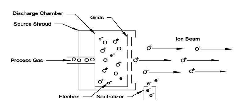
Figure 1. Schematic of an Ion Beam Source
The different types of ion beam sources are delineated by the specifics of the four (4) key elements. In this introduction, ion beam sources will be classified as either direct current (DC) or radio frequency (RF). A brief, physical description of each of the four elements is presented below.
Discharge Chamber - the discharge chamber is where the source gas is ionized.
For DC sources, the discharge chamber is referred to as the body. The body will have a magnetic field produced using permanent magnets. The purpose of the magnetic field is to control the motion of electrons such that they have several ionizing collisions with the source gas occur before being collected on the anode.
For RF sources, the discharge chamber consists of a dielectric material permeable to the RF field produced by the antenna. The RF field ionizes the source gas introduced within the discharge chamber.
Electron Source – mechanism by which electrons are produced to ionize the source gas.
For DC sources, the electron source can be either a hot filament or a hollow cathode. Typically, a filament consists of a tungsten wire which is heated to emit electrons. A hollow cathode is a device which produces electrons by locally ionizing its own feed gas. The electrons from either the filament or hollow cathode are then used to ionize the source gas, which, for the hollow cathode case, may be the same gas it used. The electrons have several ionizing collisions before being collected at the anode surface in a DC source.
For RF sources, the RF field energizes free electrons in the working gas. The energetic electrons have ionizing collisions with the source gas thereby producing ions and additional electrons. As ions leave the discharge chamber, electrons are collected on the screen grid surface.
Grids – the electrostatic apertures by which the ions from the discharge are extracted.
Grids are electrodes separated from each other by a few millimeters. Each grid has several apertures that are aligned and allow for the extraction of ions. The grid closest to the discharge chamber is referred to as the screen (or S) grid. Moving downstream, the next grid is referred to the accelerator (or A) grid. On some sources, a third grid is used which is the furthest downstream from the discharge chamber and it is referred to as the decelerator (or D) grid.
The grid assembly extracts ions from the discharge chamber by applying specific potentials (or voltages) to each grid. A potential (or voltage) diagram of the ion acceleration process is presented in Figure 2. First, the S grid is biased positive (beam voltage) with respect to ground and consequently the plasma in the discharge chamber is also biased positive with respect to ground. Next, the A grid is biased negative (accel voltage) with respect to ground and establishes an electric field along the source centerline. Positive ions in the discharge chamber that drift close to this electric field are accelerated.
Even if the D grid is not used, the potential downstream from the source is ultimately approximately zero. Depicted in Figure 2 is the electric potential for a 3-grid assembly. The D grid potential is typically held at ground potential (or 0 V). The accelerated ions then decelerate after passing the A grid and exit the aperture with a net, ion energy of approximately beam voltage. As depicted in Figure 2, electrons either located in the discharge chamber or downstream from the source are separated due to the established electric field.
Ions extracted through the grid apertures comprise individual beamlets and a typical grid assembly will have numerous apertures. As a result, individual beamlets combine to form a more, broad ion beam.
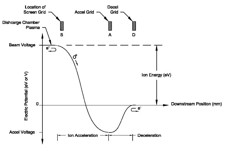
Figure 2. Schematic of the ion acceleration process.
Neutralizer – an electron source downstream from the ion source.
For DC sources, the neutralizer can be a hot filament, hollow cathode, or plasma bridge type. A plasma bridge neutralizer (PBN) is where a hot filament is placed in a smaller discharge chamber through which an inert process gas is supplied. For RF sources, the neutralizer can be either a PBN or RF type. The RF neutralizer (RFN) consists of a small discharge chamber with an RF coil. The RFN utilizes a collector and keeper to emit electrons.
The purpose of the neutralizer is to emit electrons into the environment downstream from the ion beam source. The emitted electrons provide a charge balance for the ions leaving the source. Typically, more electrons are emitted from the neutralizer than ions from the source. This is done to minimize and/or eliminate the space or surface charging that may occur. In most situations, electrons from the neutralizer do not directly combine with the ions in the beam to form high energy neutrals.
Source Parameter Definitions
As electrical devices, ion beam sources require power supplies. Presented in Figures 3 and 4 are the electrical schematics for typical DC and RF sources, respectively.
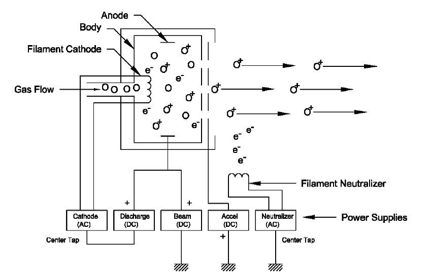
Figure 3. The electrical schematic for a filament DC source.
In Figure 3, the electrical connections for a filament cathode and filament neutralizer DC source are presented. The cathode is heated using an AC power supply. Electrons leaving the filament are collected at the anode with the discharge supply, a DC bias supply. The beam supply, also a DC bias supply, is also connected to the anode and biases the discharge plasma positive with respect to ground. Not illustrated, but commonly used is a resistor placed between the body and anode. The body resistor establishes the proper bias between the anode and body and thereby directs electrons to be collected on the anode surface. The accelerator supply, a DC type supply, biases the accel grid negative with respect to ground. Finally, the neutralizer filament is heated using an AC power supply.
In Figure 4, the electrical connections for a RF source with RF neutralizer are presented. The RF coil for the discharge chamber is energized by the RF supply and is tuned by using a matching network. The beam supply, a DC bias supply, is connected to the screen (S) grid in order to bias the discharge plasma positive with respect to ground. The accelerator supply, a DC type supply, biases the accel grid negative with respect to ground. Finally, the RF neutralizer utilizes an RF supply and matching network for its own discharge and additional DC supplies to emit electrons.
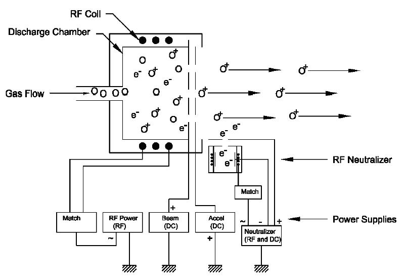
Figure 4. Electrical schematic for a RF source.
Additional power supply details and source parameters are presented in Tables 1 and 2. Ion beam source parameters used by both DC and RF sources are presented in Table 1. Specific parameters that pertain to DC filament, and RF sources are outlined in Table 2. Actual values for these source parameters will be specific to source type, size, grids, and process. Typical values will be given where appropriate.
Table 1. Ion beam parameters for all sources.
|
Parameter |
Definition |
Unit |
|
All Sources |
||
|
Source Gas Flow |
Process gas delivered to the discharge chamber |
sccm |
|
Beam Voltage |
Positive voltage applied to the discharge plasma. |
V |
|
Beam Current |
The total ion current extracted, or leaving the source. |
mA |
|
Accel Voltage |
Negative voltage applied to the accelerator (A) grid. |
V |
|
Accel Current |
Charge-exchange current collected by accelerator (A) grid. |
mA |
|
A/B Ratio |
Ratio of accel to beam currents. Indicates quality of grid focusing. Typical A/B is < 10%. |
% |
|
Neutralizer Emission Current |
The electron current emitted by the neutralizer. |
mA |
|
E/B Ratio |
Ratio of neutralizer emission to beam currents. Typical E/B is >100% to minimize space charging, surface charging and arcing. |
% |
For DC sources, beam voltage is applied to the anode. For RF sources, beam voltage is applied to the screen (S) grid.
Table 2. Ion beam parameters for specific types of sources.
|
Parameter |
Definition |
Unit |
|
DC Filament Cathode (FC) / Filament Neutralizer (FN) |
||
|
Cathode Filament Current |
The electrical current applied to the filament cathode. This current heats the filament so that electrons are emitted from its surface. |
A |
|
Discharge Voltage |
The voltage established between the filament cathode and anode. This determines the electron energy for ionizing collisions in the discharge chamber. |
V |
|
Discharge Current |
The electrical current established in the discharge chamber between the filament cathode and the anode. This current controls the ion production rate and to first order, the beam current. |
A |
|
Neutralizer Filament Current |
The electrical current applied to the filament neutralizer. This current heats the filament so that electrons are emitted from its surface. |
A |
|
RF with RF Neutralizer (RFN) |
||
|
RF Forward Power |
The RF power applied to the matching network. This power controls the ion production rate and therefore, the beam current. |
W |
|
RF Reflected Power |
The RF power reflected from the matching network. Typically, the reflected power is <1% of the forward power. |
W |
|
RFN Forward Power |
The RF power applied to the matching network. |
W |
|
RFN Reflected Power |
The RF power reflected from the matching network W |
W |